 |
Pictures of the Fermilab Detector from the 2001 Lead Teacher Institute |
|
|
|
Pictures of the Fermilab Detector from the 2001 Lead Teacher Institute |
|
|
|
|
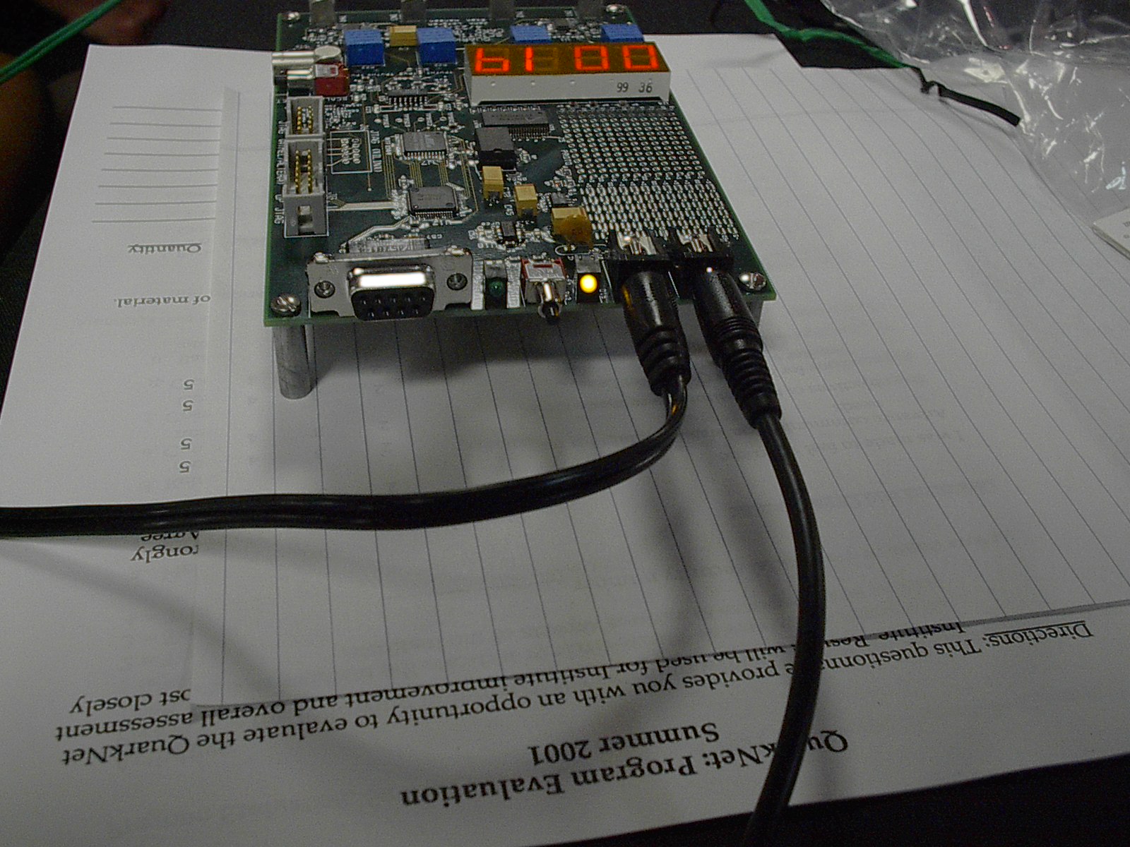
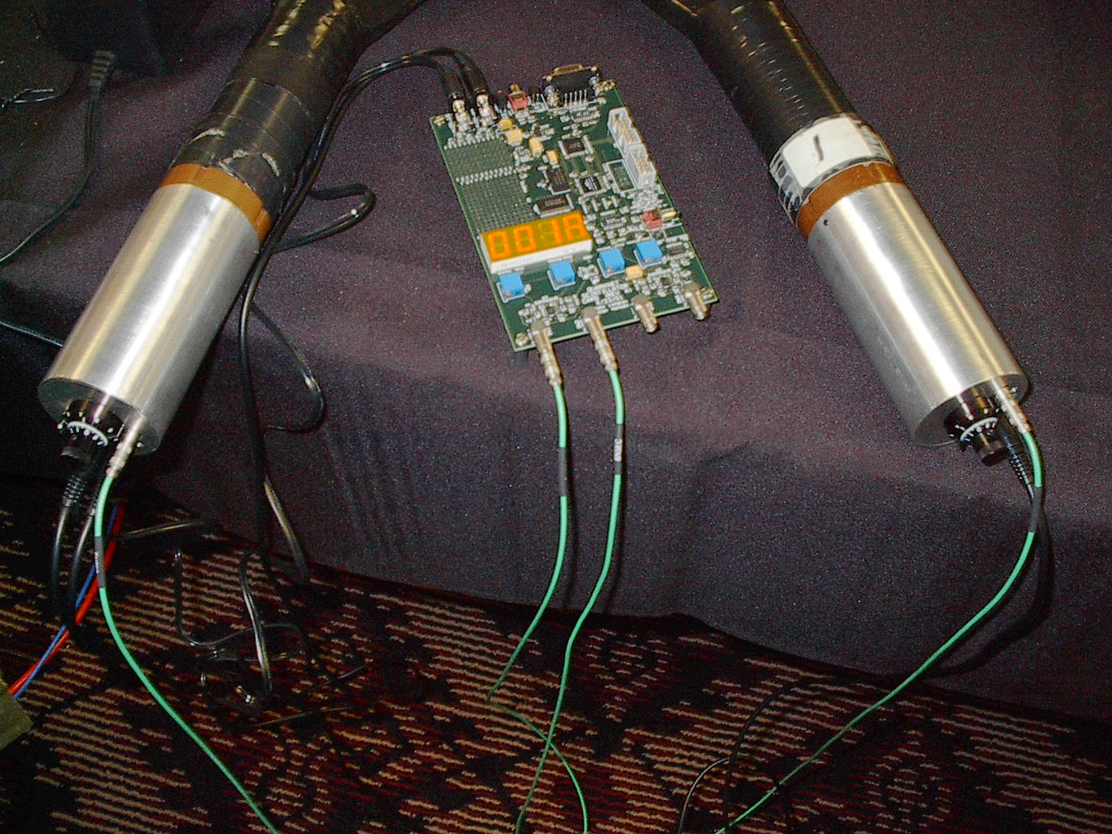
The DAQ board with LED readout; the black voltage cords are in place. |
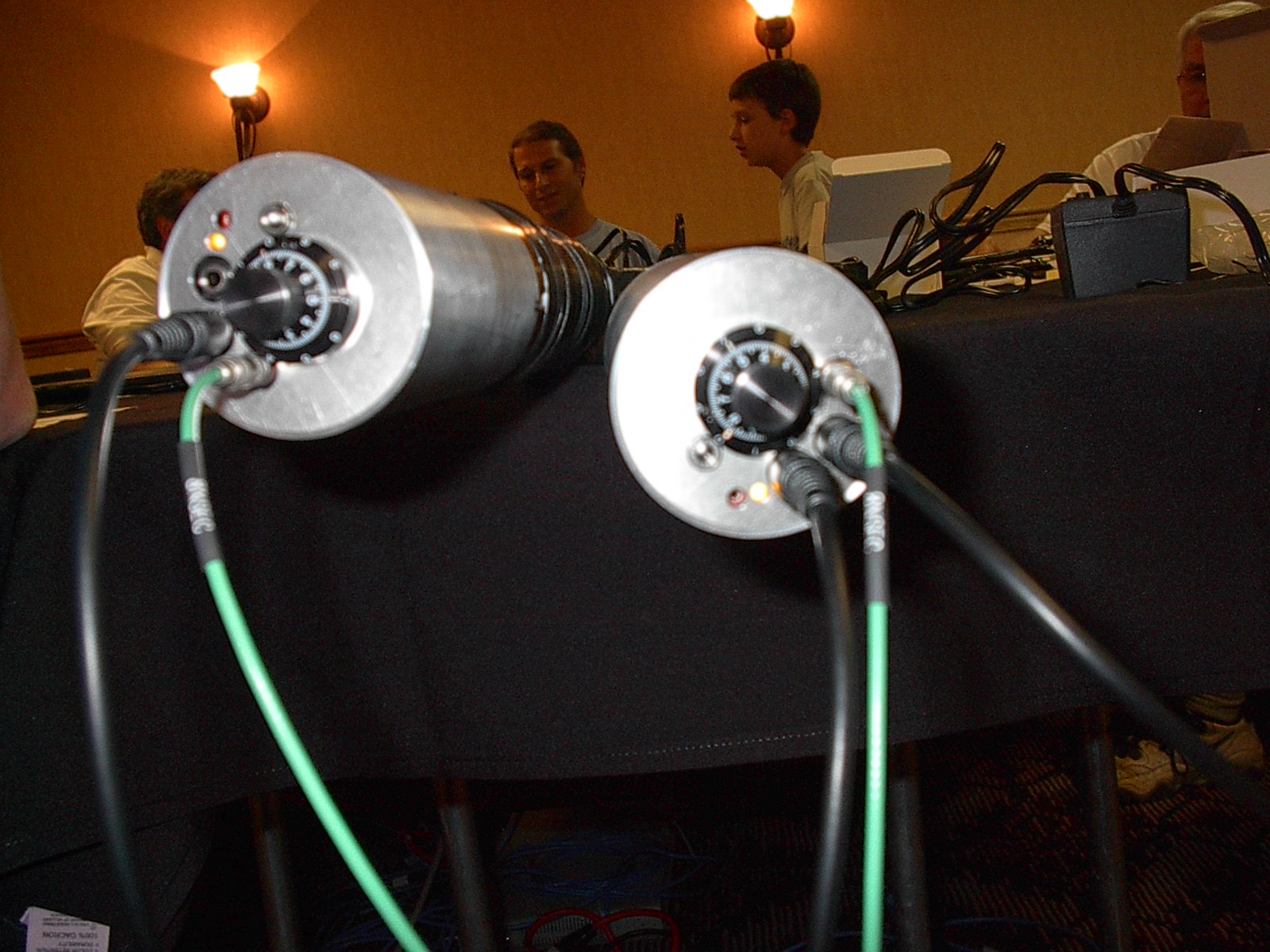
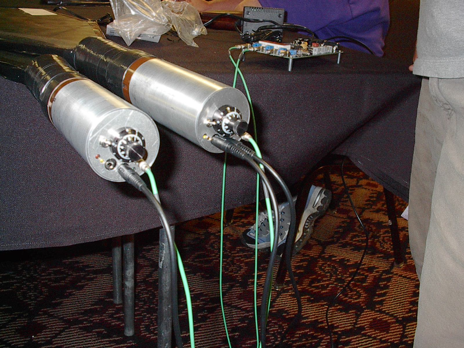
The ends of the counters showing Cockcroft-Walton bases . . . note the voltage adjustment knob on each. |
|
|
|
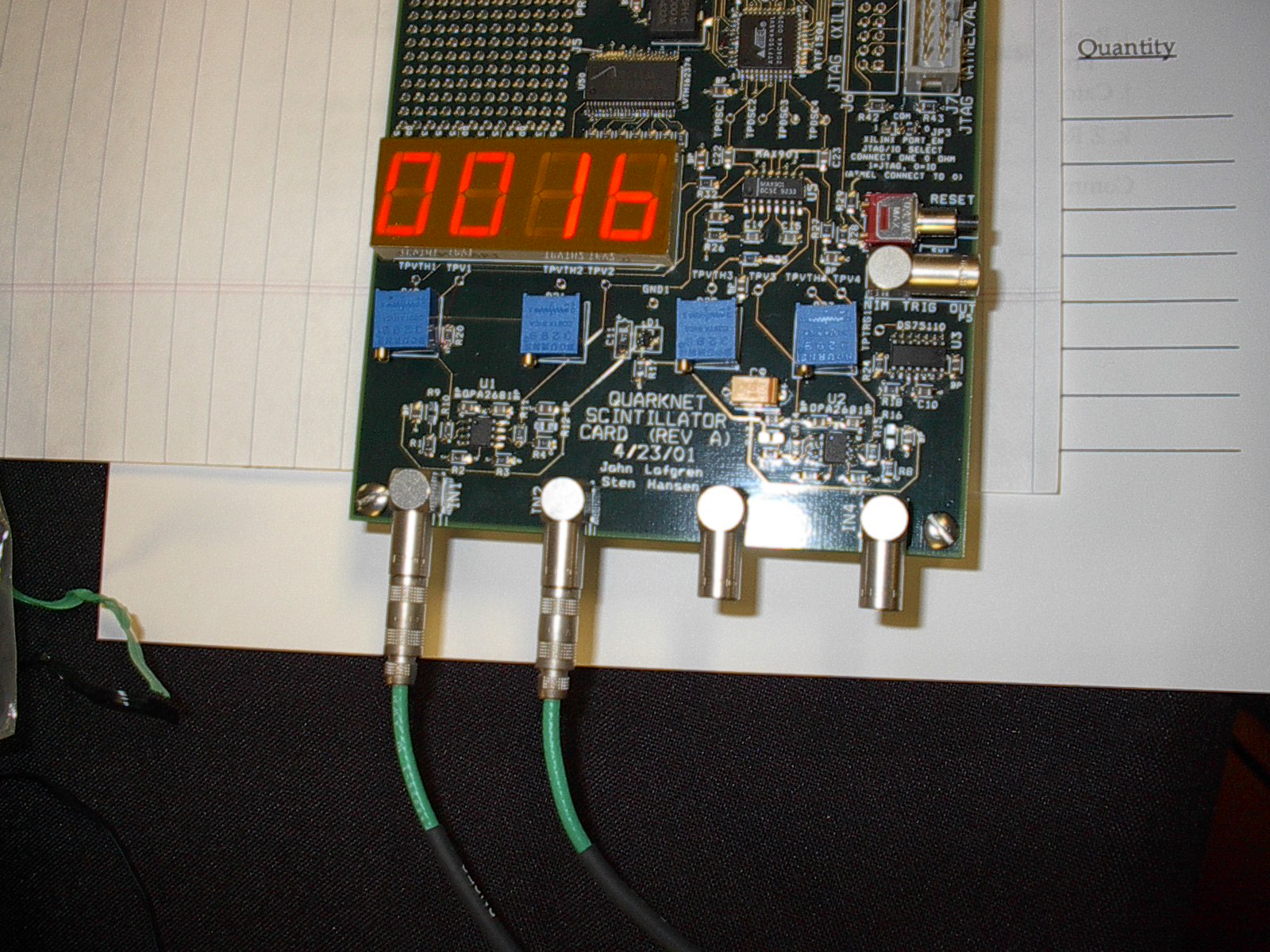
Another view of he DAQ board, showing the green signal cords. |
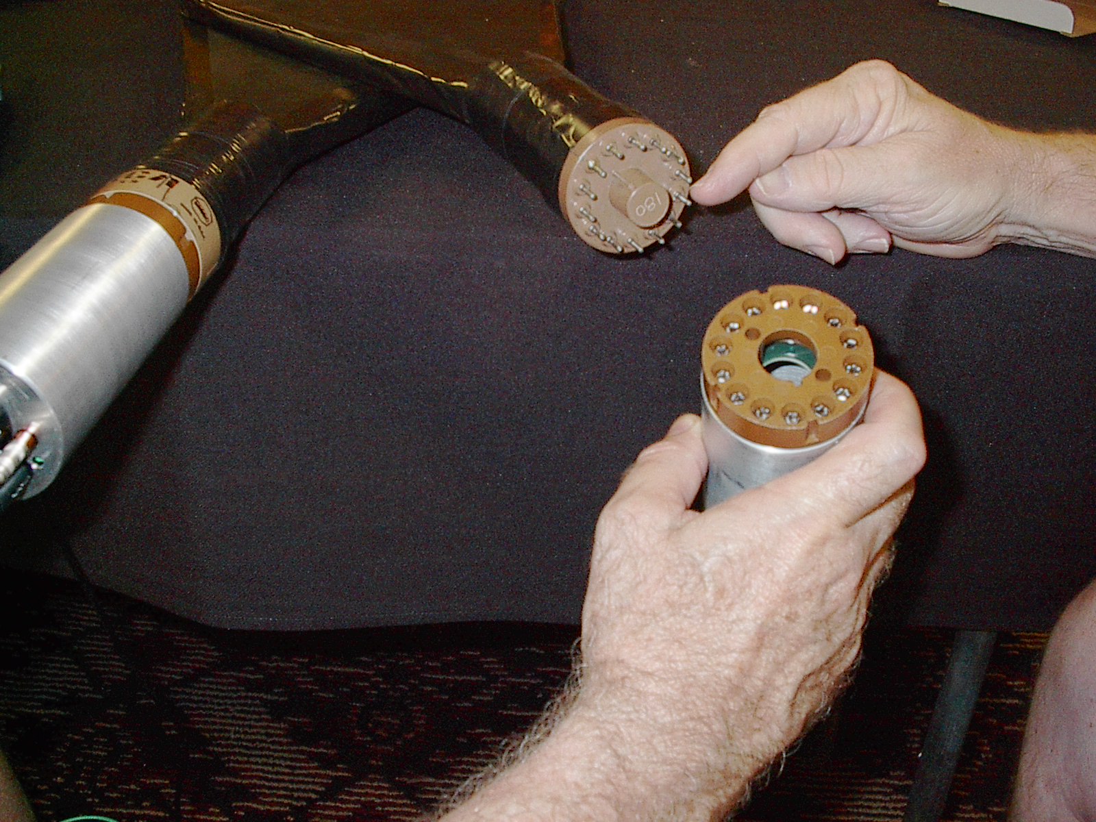
Connection of the Cockcroft-Walton bases to the PMTs. |
|
|
|
PMTs, bases, and DAQ with the green signal cords connected. |
The entire set-up: everything is connected! |